|
|
|
The
Unified Development Process
 |
Development
methodologies |
| |
The
development process of any software is the set of various
actions needed for the transformation of users' requirements
into program system. The problem of the software product development
turns to the difficulties of developers having to overcome
a lot of obstacles, before the ready-to-use product will be
handled to customer. To develop the qualitative software product
the process is necessary, which has control over the activities
of all the participants (consumers, users, and developers),
directs who, what and when has to do and how to reach the
set objective.
Nowadays, the Unified Development Process (UDP) is the most
advanced technology, describing the process of the software
design. That’s why we use in our work the methodology and
base work processes, described in UDP. According to the UDP,
the product development is based on three fundamental principles: |
| |
|
| |
 |
1.
The process is controlled by
use cases |
| |
The
use case - is the sequence of actions, running in the
system as the result of its interaction with user. They
form the principal part of the system functionality
and their entire definition allows describing the system
functionality in full extent. To determine the use cases
it is necessary to answer the question what the system
is to do for each user.
The use cases are not only the means to describe the
requirements to the system. They direct its design,
implementation, testing e.g. the whole development process.
Grounding on the use cases, the developers create the
series of design and implementation models. The testers
check the components in order to insure the correctness
of fulfilment of the use cases. Thus, use cases initiate
the process of design and generate the workflow. |
| |
|
 |
2.
The process is oriented to architecture |
| |
Architecture
is the entire project representation, where the most
critical composing parts are selected without complementary
details. The role of the program architecture is similar
to the role of architecture in building construction.
This is the framework, the skeleton of any software
system, on which the required functionality is "hung
on" in the course of time. The conception of system
architecture comprises its most important static and
dynamic aspects. The architecture must be planned to
allow the system to evolve not at the development moment
but in the future as well. |
| |
|
 |
3.The
process - interactive and incremental |
| |
This
principle presumes the program design strategy relied
upon the small controlled pieces:
- We
plan the small piece;
- We
specify, design and realize the small piece;
- We
assemble, test and execute the small piece.
The
plan for realisation of the iterations is composed to
manage them. The sequence of the iterations fulfilment
is determined with two factors. For the first, the use
cases are realised during current iteration, which increase
the product usability, for the second, the most serious
risks are removed during the realisation. The result of
realisation of the chosen use cases is the executable
code. The advantages of iterative development:
- The
financial risks are limited to the expenses for one
iteration.
- The
risk of delivery out of the planned term is diminished.
- The
consumer has the possibility to make the alterations
during the development process.
The
main tool for the description of Unified Process is UML
- the language for visualisation, construction, description
and documentation of the program system development.
|
|
| |
|
 |
The
product life-cycle |
| |
As
a rule, the program product development is very complicate
process for the integral perception. Therefore it is necessary
to separate the whole amount of work into small parts, more
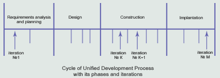
convenient for the understanding. In UDP the life-cycle time
is divided into four phases: analysis and requirements planning,
design, implementation and testing, and within the stage into
the iterations. Each this phase has own goals and tasks, as
well as fixed criteria for the estimation of the work results
on each of them. The five cardinal base processes inside the
each iteration can be defined: determination of requirements,
analysis, design, implementation and testing. This allows
marking out the set of actions and the sequence of their fulfilment,
as well as the set of documents and schemes going with on
the output of every process.
In every phase the principal volume of work falls on different
work processes and is determined with its main task. |
| |
 |
| |
|
| |
 |
1.
Analysis and requirements planning phase: |
| |
The
main objective of this phase is the determination of the
purpose for the creating product, diminishing the most
dangerous risks and business-plan preparation, exact enough
to make the decisions about project approval and launch.
It is needed to create the business-plan:
- To
define the boundaries of the intended system;
- To
determine and describe in brief the intended architecture,
in particular, its new and risky parts;
- To
find the most dangerous risks and the ways to reduce
them;
- If
it is necessary, to construct the conceptual prototype;
|
| |
|
 |
2.
Design phase |
| |
The
main objective for the design phase is the creation of
steady architecture, on which the system base will be
build. Besides, it is necessary to conduct the study of
the intended system for the next phase planning. For this
it is needed:
- To
create the base level of architecture;
- To
determine the risks, which can have an effect on expenses
and the implementation of the schedule of work and
the ways of their decreasing (removal);
- To
cover with the use cases the most part of functionalrequirements;
- To
make the financial plan, to appoint the stuff and
expenses, grounding on the business practice
|
| |
|
 |
3.
Construction phase |
| |
The
main objective is the creation of product ready to beta
testing. This is the most long-lasting on time and most
resource-consuming phase. Usually it includes the big
number of iterations. As a rule, up to 90 per cents of
use cases are not detailed, at the beginning of construction
phase. The list of work comprises of:
- determination
of extended description for the use cases;
- completion
of analysis, design and testing;
- preservation
of architecture integrity and its modification in
the case of necessity;
- tracking
of risks, revealed during two first phases.
|
| |
|
 |
4.
Implantation phase |
| |
Implantation
phase begins with system transferring to the users’ environment
and its beta testing. The main objective is the assurance
that the built product fully corresponds to the consumer’s
requirement. The next tasks should be done on the Implantation
phase:
- The
preparation of places for the deployment;
- The
determination of requirements for the environment
modernisation;
- The
development of guidelines and other documentation
for the product;
- The
modifications applying to insure the efficiency under
current environment condition;
- The
correction of the revealed defects.
The
implantation phase is ended with formal release of product.
|
| |
|
|
| |
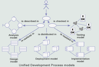
The result of every
cycle is new release of system, and
every release is the ready-to-shipment
product. Besides the source code,
ready to compilation, the product
includes the set of visual models
of system and architecture description.
The set of these documents allows
making alterations to system much
easier or modifying during the exploitation
process. |
| |
 |
| |
|
 |
Subject
area model or business-model |
| |
|
| |
The construction
of business-model implies the marking out of use cases of software
and business-entities, which will be maintained with software.
The objects of the subject area usually describes:
- the
entities, used in business, such as applications, invoices
and contracts
- the
objects and notions in real world, which the system must
watch
- the
events, which will occur or occurred, for instance, the
gear halt, the temperature increase
The subject
area determines the most important objects’ types in context
of system. |
| |
|
 |
Use
cases model |
| |
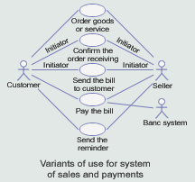
The use
cases model is something similar to the convention between consumers
and developers on requirements, which must satisfy the system.
It gives the needed data for the further analysis, design and
esting. It includes sets of actants, use cases and determines
their interdependencies. |
| |
 |
|
- Actants
are the extra-system agents which interact with system.
- Use
case is the part of functionality, which system grants to
actants to acquire the significant result.
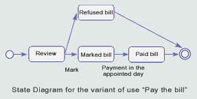
For the use
cases events stream detailed description the state diagram,
on which all possible system states are depicted (initial, intermediate,
final) is used. The states diagram is supplied with detailed
text description for the running processes. The use cases model
describes the common developers’ and consumers’ opinion on the
requirements to system. |
| |
 |
| |
|
 |
Analysis
model |
| |
|
| |
The
analysis model is the conceptual model
of the object, in which the requirement
analysis is made. In the course of
analysis the requirements are made
more precise and structured. The analysis
model comprises of the analysis package,
analysis classes and the analysis
of implementations of use case.
- The
analysis class is focused on the
functional requirements. It can
always be referred as one of types:
boundary, control or entity. The
boundary classes are used for
modeling the interactions between
system and actants. The entity
classes are destined for modeling
the informational filling of the
system, and they describe the
real world objects. The control
classes are responsible for the
objects interaction and management.
- The
analysis packages provide with
the means for organisation of
the analysis classes and implementation
the use cases as logical blocks.
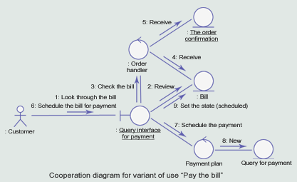
- The
analysis of implementation of
use cases describes how the given
use case is realised and how it
is executed in the terms of analysis
classes and interacting analysis
objects. It consists of text description
of the events flow, the class
diagram, and interaction diagram
in the definitions of analysis
model.
The analysis
model contains the exact and plain
in using description of the requirements
to system.
|
| |
 |
| |
|
 |
Design
model |
| |
The design
model describes the physical implementation of use cases. It
is used as initial data for implementation. It comprises the
design subsystems and service subsystems, interfaces, design
classes, use case projects. |
| |
|
| |
- The
design subsystems and service subsystems are usually described
on the base of analysis packages. They serve to organise
the constituent parts of design model into easy controlled
parts. They comprise of design classes, realisations for
the use cases, interfaces and other subsystems (recursively).
- The
design classes are the most approximate to real class implementation
of its abstraction. To describe it, the selected programming
language is used, the visibility of attributes and methods
is given. The design class can be active, that is to say
the objects of class use its own logic for control, working
concurrently with other active objects.
- The
project implementation of the use case determines the description
for the concrete use case in the terms of design subsystems,
design classes, and their objects. It consists of the text
description for the events stream, the class diagram, diagram
of collaboration in the term of design model.
- The
interfaces are used to assign the operations, run by the
design class or subsystem. This is the variant for the separation
of functionality specification from its implementation.
|
| |
|
 |
Deployment
model |
| |
|
| |
Deployment
model portrays the physical way of
the system functionality allocation
on computational nodes. Each node
is the computational resource (processor
or other unit) and connected with
other nodes through the channels for
information interchange (internet,
intranet and so on). The functionality
of each node is determined with components,
which will be deployed on it. |
| |
 |
| |
|
 |
Implementation
model |
| |
|
| |
Implementation
model describes how the design elements such as design classes
are implemented. It comprises of the realisation subsystem and
components. |
| |
 |
| |
- The
realisation subsystem defines the way of data storage, inherent
to that or either development environment: Java package,
the project in VB, C#, the directory in C++ and so on.
- The
component is the physical container for elements of the
design model. Usually they represent such conceptions as:
“executable module”, “source file”, “library”, “table”.
|
| |
|
 |
Testing
model |
| |
Testing
model describes how the executable components of realisation
model are examined with the help of integrity tests and system
tests. Testing model is the set of test examples, testing procedures
and test components.
- The
test example determines the way for test of the system and
comprises the subject of test together with the initial
data and the result, and the conditions for test.
- The
testing procedure determines the instructions for the execution
of the separate example or its part.
- The
test component automates one or few test procedures or its
parts.
|
| |
|
 |
Architecture
representation |
| |
Architecture
representation contains the extracts form above-written models
for system, which are important for the architecture design.
All these models are linked between each other. They are created
and supplemented during the whole cycle of the product development
while subsequent implementation of actions, which are determined
for every work process. On the next cycle of development availability
of these models allows the developers to obtain the full comprehension
of the existing product. |
|
|
|
|
|